This post deals with the cleaning, repairs, and restoration work on the movement from my
John Birge & Co. 1848 Column & Cornice Clock.

I think it's fair to say that this movement was a wreck! It was full of botched repairs, solder, and damaged components, I spent at least 8 hours cleaning, repairing, and adjusting this movement over the past 2 days. The movement had enough problems that I thought I might simply swap the whole movement with a spare Birge & Fuller movement that I have, but unfortunately the spare movement I have has the Birge & Fuller stamp on the front plate, and this movement that's original to the John Birge & Co has no name on the plates.
The good thing about having the spare movement, as well as my other original Birge & Fuller column clock (in my collection) is that I could refer to both of them during my repairs.
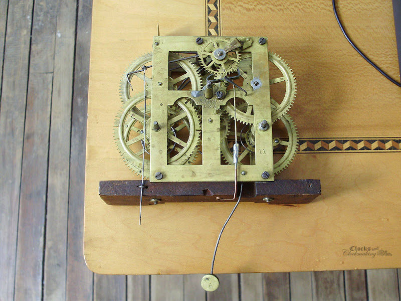
For now, here are a few "before" photos, and some details related to the problems in need of attention:

The bulk of the issues can be seen in the following photo:
- poor quality and mangled "helper springs" attached to the levers (which are entirely unnecessary in this particular movement)
- crutch wire broken and soldered in 3 places
- all levers and wires horribly bent, kinked, and mangled, some of which have even been clipped short
- entirely replaced and poorly functioning fan assembly
- globs of solder
- the "spade" end of the count hook is broken
- missing pins
- bent pivots
- punch marks around pivot holes
- mangled winding squares
- missing strike advance lever
- incorrectly sized cords
- lots of dirt and some rust

This shows the worst pieces (the two upper wheels had bent pivots):

All the wires were mangled.

Also not clearly visible was the "repair" to the fan's bushing, which is inset into a deep hole, and held in place purely with solder:


Initially I thought I could reuse the existing fan arbour and lantern pinion assembly, but it was a very poor fit. Here I had simply removed all the solder, and knocked the pieces apart.

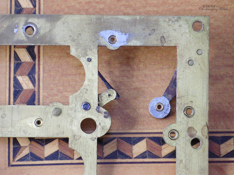
As I was heating and removing the solder (simply using a small torch and a brass wire brush) I made the grizzly discovery of 3 holes along the rear top plate (near the fan pivot hole).


The smaller holes were enlarged slightly with a cutting broach (mostly to remove all the excess solder), and brass rivets were installed. For permanently plugged holes, I simply cut a small countersink on both sides, and gently hammer a piece of brass on both sides to essentially form an "I" shaped plug. These are then filed and polished flat. The large hole was also slightly enlarged, but I left some of the oval shape. The brass rivet material (any brass scrap) was heat-treated first so that it would better fit and fill-in this slightly ovate hole. The hammering and peening actions re-harden the brass. Be sure to work from both sides equally.

Filing:

Not the best photo, but you get the idea. It's not going to be 100% perfect, but it looks a lot better than the extra holes.


This shows the repair after the new pivot hole and fan were fitted. The location for the hole was marked using a caliper to measure the centre based on the front plate.

The end of the count hook was repaired by filing a fresh surface on the interior side of the remaining stump, and silver soldering a small piece of steel mainspring material onto it. Once it's cooled, the excess steel is filed away to an acceptable shape, and polished smooth.

The warning lever had been clipped short, so using the dimensions from my two existing movements as a guide, I made a half-lap joint and silver-soldered a new length of wire to it.

The excess borax flux and solder can easily be filed away, and a bit of sandpaper and steel wool help to blend in the repair.

These photos show all the repaired levers:


When I had removed all the soldered pieces from the verge, I found only the top crutch with about 1/8" stub of the brass crutch wire left. This was essentially useless, so the nub was removed with a punch, and a new brass crutch wire was installed. The top of the new wire was attached with a friction fit alone. To do this, I hit the wire with a small hammer about 1/8" down from the tip. Just enough to BARELY oval the wire. The wire was then pushed through the hole in the crutch, and held from below in a small vise. The top of the wire (inside the crutch) was then hammered down firmly (like a rivet). Since this is brass wire from a horology supply house, it's fairly stiff. To form the bottom loop, I was very careful to heat-soften the wire at each bend to avoid having it break. The bottom loop is made into a figure 4, and the excess stem was cut flush using a jeweler's saw (which is much easier than trying to clip it with pliers or nippers.

The new fan was a fairly long job on its own. I was able to use a prefabricated pivot and lantern pinion assembly, which I then cut to size. A pivot was formed on the end, and a new pivot hole was drilled into the back plate (in the original location). Once that was done, and the pivot hole was broached and both wheels spun freely (this lantern assembly turned out to be a perfect fit on my initial testing), I then cut a new fan blank (again referring to the size on the original spare movement). The centre divot was formed with a piece of 1/8" steel wire pressed in place with a block of soft wood on the back side, and hardwood on the front.
At this point, I noticed that the fan would not have enough clearance. This is because my lantern pinion assembly sat at a different depth than the original. To get around this small problem, a rectangular notch was filed into the fan to contour the pinion cage. Once the fit was good, a small notch was filed into the arbour, and holes were drilled into the fan for the tension wire.
The last step was to attach the warning pin. A small flat was filed onto the arbour, and centre punched for the hole. The rest was simply drilling the hole, and fitting a friction-fit piece of steel wire, bending it to the correct shape, and trimming it.

The lever with the J hook had 2 additional holes in the stem. I have no idea why they were there, and one even had the remnant of a piece of steel wire in it. The holes are either a later (botch) repair, or an original factory error. In either case, the two levers are in the correct locations (again, checking with my 2 other movements), so I decided to just plug these. The easiest method is to either use taper pins, or suitably sized soft steel wire. The same peening method used earlier was employed.


So after all that work, I was finally happy with everything, the levers were all adjusted (even the hammer tail was at the wrong angle), and everything is back together and functional again.
The movement was finally cleaned and reassembled this afternoon. It did not clean-up nearly as well as I had hoped, so it was given a soft polish all over with ultra fine steel wool.