Showing posts with label Solder. Show all posts

Wednesday, February 24, 2016

Rosewood Seth Thomas (Thomaston) Ogee Clock - Part 1

I'm starting this off with the restoration of the movement, simply because I haven't photographed the finished case yet. The "before" photos can be seen in this post: http://jcclocks.blogspot.ca/2014/06/clock-haul-4-new-acquisitions.html. Most of the clocks that I bought from this sale (now a good client of mine) were in relatively decent shape, yet still in need of work. Either case restoration, movement restoration, or dial restoration (or all three).

On this Seth Thomas clock, it needed all three. The dial had been very poorly repainted, the veneer had chips, and the movement (which is the subject of this post) was not in excellent condition.

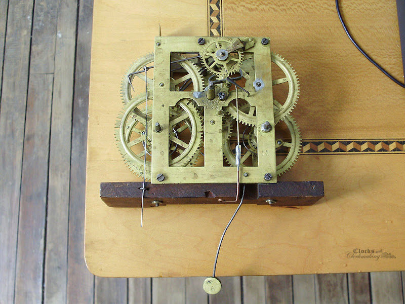
Here is the movement "as found". Overall not too bad, but in need of some attention. This is a Type 1.242 movement. Note the use of screws to fasten the top plate, and the semi-circular projection on the plates by the time second wheel pivot. I wasn't able to find manufacture dates for this specific movement, but I would guess early 1870s.


Note hole-closing punch marks (not repairable), and a few new bushings.


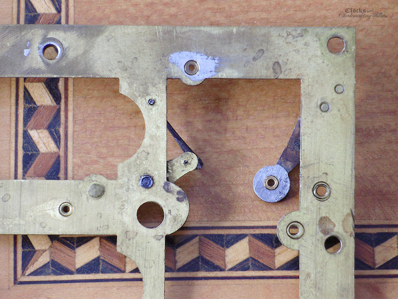
Lots of solder, and note the damage to the screws.


A creative (and strong) repair to the crutch wire. While this is certainly strong and durable, it is far from elegant.


Upon disassembling the movement, I discovered that the fan wheel had been soldered.


I don't know why the escape wheel bushing is so ridiculously long. With a larger surface area (metal on metal contact), the clock needs more power to drive it. This is one of the reasons why clocks with very thick plates have deeply cut "oil sinks" for the pivots. In those cases the plates are thick for strength (and looks) and the "oil sinks" are to reduce the thickness and contact area. In this case, the bushing is twice as deep as it needs to be.


Most of the work on this movement (even though it looked rather bad) was simply cleaning and solder removal. On the areas where the solder was just a very thin film, abrasives were used. I used very fine sand paper (maybe 320 grit?) followed by finer grit, and #0000 steel wool. On any heavier areas, the excess solder was heated and "brushed off" the surface before sanding and polishing.

The excessively thick bushing was filed down, and given a light peening. This closed-up the pivot hole slightly, so it was opened-up again with a cutting broach.

The following photos show the repaired (cleaned) areas before cleaning the movement and wheels in cleaning colution.


I don't have photos of the fly wheel repair, but the solder joint was a cold one, and I was able to take it apart easily.

The crutch wire repair was done using a half-lap joint (splice) using a new piece of brass wire. You can spot the joint just over the spoke of the main wheel.

In addition to this, the screws were repaired (mangled sections cleaned with a file, and new bluing applied).


The movement did not come out of the cleaning solution as nice and shiny as I had hoped, so the parts and frame were given a light polish with #0000 steel wool.

Sunday, March 10, 2013

Repairing Antique Clock Hands

Clock hands are one of the most important visual elements on a clock. They are usually made of fairly thin, and delicate steel, blued, and abuse suffered from mishandling them, or forcing them, can wreak havoc on them over time. The hands from this longcase clock are no exception.

As a general rule, heavy steel hands are easier to repair, since they are thicker and sturdier than very thin (more mass-produced) examples. Both types of hands, however, can be repaired in the same manner.

Repairing hands is relatively straight forward: Mend the break with a supporting piece on the reverse. Actually executing the repairs, however, can get very tricky.

In the case of the hands on this particular clock, we have two repairs to make (one on each hand). The hour hand was broken in half at some point, and simply repaired with an overlapped solder repair. The minute hand is missing about 3/4" from the tip.

As received:


To start, you will need to find suitable "patch" material. Ideally, you want thin steel with a good carbon content (such as spring steel, which isn't very flexible). Any usable scrap steel can be used. Thin saw blades, taper pins (which would need to be filed flat on two surfaces), or strong sheet metal. Keep in mind that the patch steel will now be taking the job of transferring the force applied to the hand, so you want a stiff metal. Try to stick to something relatively thin. A hacksaw blade could work, but it's getting a bit on the thick side. For this hand, I used a piece of relatively thick spring steel (scrap metal).

Coarsely cut or grind your patch to the correct width. You will want to cut it long enough to hold a good solder bond on each side of the break.

In this photo, you can see the patch piece, and the hand, which has been taken apart, and had the excess solder scraped away.


File, or otherwise abrade and clean the 3 surfaces to be joined (one surface of your patch, and a portion on each side of the hand - on the back).

Tin all 3 surfaces separately, and THINLY. For this type of repair, I'm using regular solder (mine happens to be silver bearing low-temp solder: 98% tin, 2% silver).


To make soldering all 3 pieces easier, I tie all the pieces tightly together using old window screen wire (visible in the photo above). This works well because the screen is aluminum. Aluminum will not stick to solder.

I also use one of those "helping hand" tools to hold the hand while it's heated.


As I mentioned earlier, these hand repairs can be tricky, and parts can move easily. Here was my first attempt:


If this happens, just desolder, re-flux, and redo the repair.

Once your pieces are properly aligned, sturdy, and cooled, you can start filing the repair. Start by squaring the edges. Once that's done, you will also want to taper all the other edges on the back in a pyramid shaped fashion. This can be done entirely by hand with files, or you can cheat and combine hand filing with the use of a grinding wheel on a Dremel tool (which is what I did).

Aim for something like this:


The purpose of tapering the repair is simply to make it look less visible from a slight angle when you're viewing the hand(s) from the front.

The front on this particular hand is not 100% perfect (especially if you're looking at an extreme close-up), but the repair came out quite well.


To finish the repair, you will need to use a cold method to colour the repair and solder, such as Gun Blue, or paint.

Here is the completed hour hand:


I didn't photograph any of the repairs to the minute hand, but I'll explain what I did.

For the minute hand, I decided to cheat and make both a beautiful, solid, and easy repair. Since the hand terminates in a very gradual point, I simply chose an appropriately shaped steel taper pin for the repair. I did not need a 3-piece repair here. I simply filed a notch into the end of the pin until the hand fit into it flush on the top surface. Once soldered, the front and back of the pin were filed down, and the repair is nearly invisible.


Back:


I have used the same techniques described above to repair other hands with equally good results.

Thursday, February 28, 2013

Longcase - Small Repairs

A lot of the repairs that are needed on this particular clock are simple (and not-so-simple) solder repairs. Some a tricky, some could potentially be a complete nightmare, but so far, so good.

Let's start with the pendulum rod and rating assembly. This was one of the first things I tackled.

You may remember that it looked like this:


There are two repairs needed here. The broken rod (with the broken tip in the top of the rating assembly), and the severely bent threaded rod.

What most people would be tempted to do is to grab a pair (or two pairs) of pliers, and attempt to straighten the threaded rod. This could work, but it could also cause several problems. In the "best case scenario" this works fine, and the rod is once again functional. However, in the "worst case scenario" you could end up snapping the rod, or crushing/marring the threads. On items this old, it's always better to tread carefully.

I chose to heat the threaded rod with a torch until the steel was soft, and then simply bend it as best as I could, using the hole in my anvil as a leverage point. This left me with a very safe repair that insured the safety of the threads, and applied very little stress on the rod. The result is not a perfectly straight "good as new" repair, but the nut moves easily from top to bottom.


For the top of the assembly, I was lucky to find that a small portion of the threaded tip was still protruding, and it came out with almost no force. I chose to use hard solder (high heat silver solder) for this repair, since it will need to handle a fair amount of stress.

Another repair option would be to re-thread the end of the rod (since only 3/16" was broken off), but it's been my experience that the threading on these is almost always "non standard". In fact, I was going to flip the rod to have the soldered repair at the top, but the threading on the suspension spring block is not the same size. Silver soldering can be tricky to learn, but it is essentially the same as regular soldering. The only differences are that you need a special solder (I believe mine is borax based) and you need to be sure that both parts being jointed together are RED HOT. If the parts are not hot enough, the solder will not flow.

One of the drawbacks of high temperature solder is that on most items, you will completely discolour the metal(s) being fused. You will also want to make a very neat repair, since the cooled solder will need to be ground or filed off.

Here is the finished repair (sorry the camera was not quite in focus).


Another quick and easy repair was the bell stand. I was able to bend the break back 95% without having it snap off, and then I soldered the break with silver solder.

Here you can see the soldered joint before clean-up. You can see how darkened and discoloured the steel is, and the silvery-gold colour of the silver solder.


Once cleaned-up, the repair (especially in a crevice like this) is nearly invisible.


Another simple repair was fixing the light bend(s) in the crank key. The key is VERY sturdy, but I was able to bend the key with just hand pressure. This "repair" isn't that much of a repair, but it does make a noticeable difference.


The last little repair (so far) was this screw. This is one of the two screws holding the bridge piece for the hands (which is also broken, and will be discussed later). It appears to have been in use "as-is", but I wanted to try to repair it.

I have NO IDEA how someone managed to split a screw in a partial spiral down the centre, but I suspect it may have been an original defect in the steel.

I used regular (soft) solder for this repair.


You can still see the split, but I didn't want to use too much solder. The head of the screw was also repaired. When I see badly mangled screws, I usually take a few minutes to file-off the marks around the slot, and improve their look as much as possible.


The next post will cover the repairs to the clock hands.