Sunday, September 18, 2016

Month-Going Longcase Clock Project Part 3 - Making a Bell Stand

Part of the restoration of the passing strike components involved replacing the missing bell stand. This is a shaped piece of steel that carries the bell.

Replacements are commercially available, and while they can look okay for certain clocks, the specific design needed for this particular clock means that it needed a custom stand. I prefer to make my own parts whenever possible, because I find that they look a lot nicer than factory made replacements.

Here's a typical mass produced replacement bell stand:


The first step in creating the bell stand is to find a suitable piece of steel, and cutting the blank. I use regular 3/4" x 1/8" steel bar stock from the hardware store. This is fairly mild steel, and it is easy to work with. The blank is cut using a hack saw. This short video shows how I cut the blank.


The rough-cut blank is then further shaped on a bench grinder, or alternatively, with coarse files.


The shape of the bell stand continues to be refined with smoothing files, and then eventually with sandpapers.


To round the stem portion, I begin by coarsely filing the corners, then filing those secondary peaks.


Once the bulk of the shaping has been done with the files, I switch to cloth-backed sanding papers, and I use this technique to round and polish the surface:


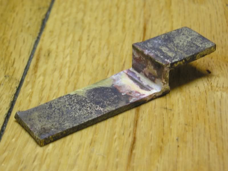
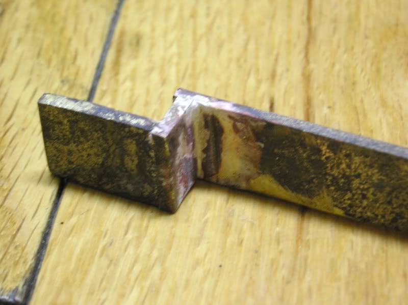
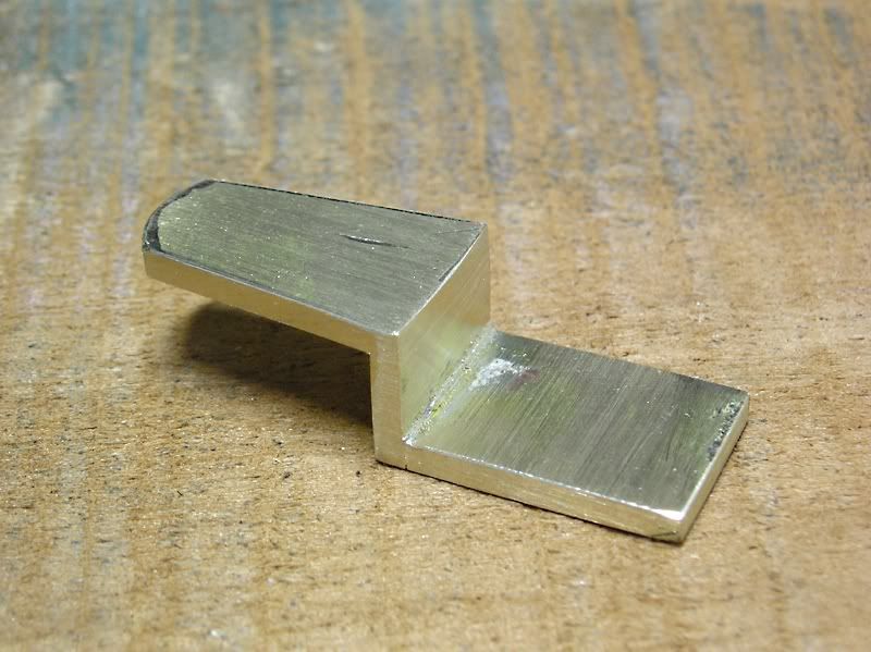
With 90% of the shaping and polishing done, I turn to the fitting of the bell stand to the movement. Normally a bell stand has a pointed teardrop shape that sits flat over the backplate, but this one has the style where the end of the tip turns into a locating hole in the plate. To form this hole, the blank is heated, and bent over an anvil.


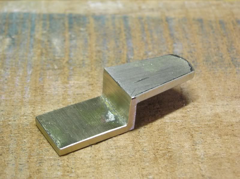
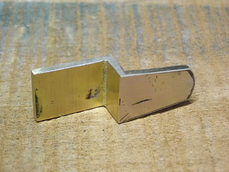
The bulk of the excess metal is carefully filed away until the profile works with the plate holes. The screw hole will be cut last.


For the top of the stand, where the bell must sit, I use just a cross-shaped design that I came up with. This is a simple design, and it has worked well on the last bells stand I made. Not shown is the threading of the top. It is simply filed roughly into a cylinder, and threaded. A square brass nut is then cut, sanded, and tapped to match.


Here you can see the bell stand fitted to the clock plate.


You can also see the bell hammer, the bell stop piece (attached to the pillar), the hammer cock and a bit of the lifting piece. The hammer spring and spring pin had not yet been fitted.


Month-Going Longcase Clock Project Part 2 - Small Parts & Repairs

In this post, I cover the repair of the motions works post, the fabrication of the passing strike components, and the fabrication of movement mounting bolts.

A small repair was made to the motion works post, because the tip had broken off at the end where the taper pin slips through. This was done with a simple half-lap joint (hand cut with files), and soldered in place.


The hammer arbour cock was fabricated with brass sheet, and the pieces were hard soldered with silver solder. The process makes for a very scary looking mess, but once everything is cleaned up, filed, and polished, it looks and works beautifully.


The hammer arbour itself is simply a stem with a pivot shaped on each end. The arbour carries a hammer stem, a lifting piece, and a stop pin for the spring.

The lifting piece was cut from 1/16" steel, sanded, polished, and drilled to fit the arbour stem.


The hammer stem was cut from 1/8" thick mild steel bar stock (available at any hardware store). The basic shape was cut out, and the stem portion was rounded and shaped. I will cover my process for rounding the stem in the next post showing the fabrication of the bell stand.


The mounting bolts were a bit fun to fabricate, but ultimately, because I changed the design of the seatboard, they will be useless. I will need to re-make longer ones. The bolts are made from 1/4" mild steel rod, ground/filed slightly thinner at the threaded tips. They are then threaded to fit the pillars (the pillars had to be re-tapped to fit a modern threading), and then square brass tips were fitted and silver soldered to the ends.


Unfortunately, I don't have all my photos in order, so I don't have all the detailed secondary photos of parts like the hammer head, and the hammer stop piece, etc. Stay tuned for the next installment of this ongoing project.

Month-Going Longcase Clock Project Part 1 - Introduction

This is a fairly ambitious project that I've already been working on for quite some time. I purchased a loose longcase clock movement on eBay back in 2009, knowing that the wheel count seemed to suggest it might be a month-going timepiece. It had obvious pieces missing, and some condition issues, but the price was fairly low.

The following photos show the movement as-received, with no repairs or cleaning done to it.

The front of the movement. Note the circular cutout on the right hand side, screw hole (and locating pin hole), and the missing pin on the small motion works wheel. This was for a passing strike system.*


The back of the movement. The hole on the left side is for the hammer arbour. You can also see the bell stand holes, and the holes for the hammer spring in the lower left. Additionally, there are two or three additional holes on either side of the crutch near the bell stand, and I have no idea why those are there.


The motion works. Note mismatched screws again.


Bridge for crutch and pendulum, showing poor repairs to the crutch (solder), evidence of the bridge being relocated (extra holes and pins) and mismatched screws. Also note the threaded hole for the bell stand.


Interior wheel train. A standard 8 day movement will have 4 wheels, and will wind clockwise, whereas a month-going clock like this one will have an additional wheel, and it will wind counterclockwise.


The escape wheel is in terrible shape, with 2 poorly repaired teeth. At one point, a slip of hardened steel was soldered to the exit pallet of the anchor. The pallets were likely very worn, and this repair is why the back bridge was raised.


A poor repair to the original brass clickspring. I love the delicate shape of the click. Also notice some severe corrosion spots to the brass in a few places.


The shadow of the hammer spring on the back plate.


Inside plates. There are several old handmade bushings installed, some punch marks, and corroded areas.


The movement came without a pendulum, hands, dial, key, or weight, but it did have the original brass pulley with it, which is really nice to have.


So with that, what is the plan, and why is this an ambitious project? Well, I want to turn this into a month-going Joseph Knibb-style ebony longcase clock, done in the style found in London circa 1680-1690. Such a clock requires a fairly short case, and a fine 10" brass dial. Adding to the challenge is that I have very expensive tastes, on a nickle and dime budget.

The case I want to copy (with some small alterations) is this Joseph Knibb longcase:


The modifications would include no opening in the trunk door (just 3 shallow panels), no panels on the base sides (panels on the 3 trunk sides only), and no satire mask decoration above the trunk door. Everything else will be basically the same. For a long time I thought of making a case with a flat top but I really liked this one. The mouldings will not be exact matches. I will get them as close as possible without having custom knives cut. The clock case will have bun feet, and a rising hood (but no spoon latch). To save money, the case will be built largely of pine, poplar, and maple, which will all be hidden by the ebonised finish. A traditional case like this is usually built from 1/4 sawn white oak, veneered in ebony or ebonised fruitwood such as pear.

The clock movement currently has all the missing components fitted: a passing strike, which is a rare find on a longcase movement, a dial, custom cut steel hands, a custom made lead weight, and a pendulum. Several of the following posts will go over the process of rebuilding all these missing components (with very limited tools), as well as building this fine case.

* A passing strike is the most simple strike system possible, and it involves the raising and releasing of a hammer to strike a bell one single blow on the hour. It is commonly used on "temple style" black mantle American clocks for the half hour bell strike. This system is also occasionally found on New Hampshire mirror clocks, and Massachusetts shelf clocks. The system uses a lifting pin on the motion works to raise the hammer. The hammer is either assisted by a spring, or falls by gravity.